KM6-II Subrack Accessories
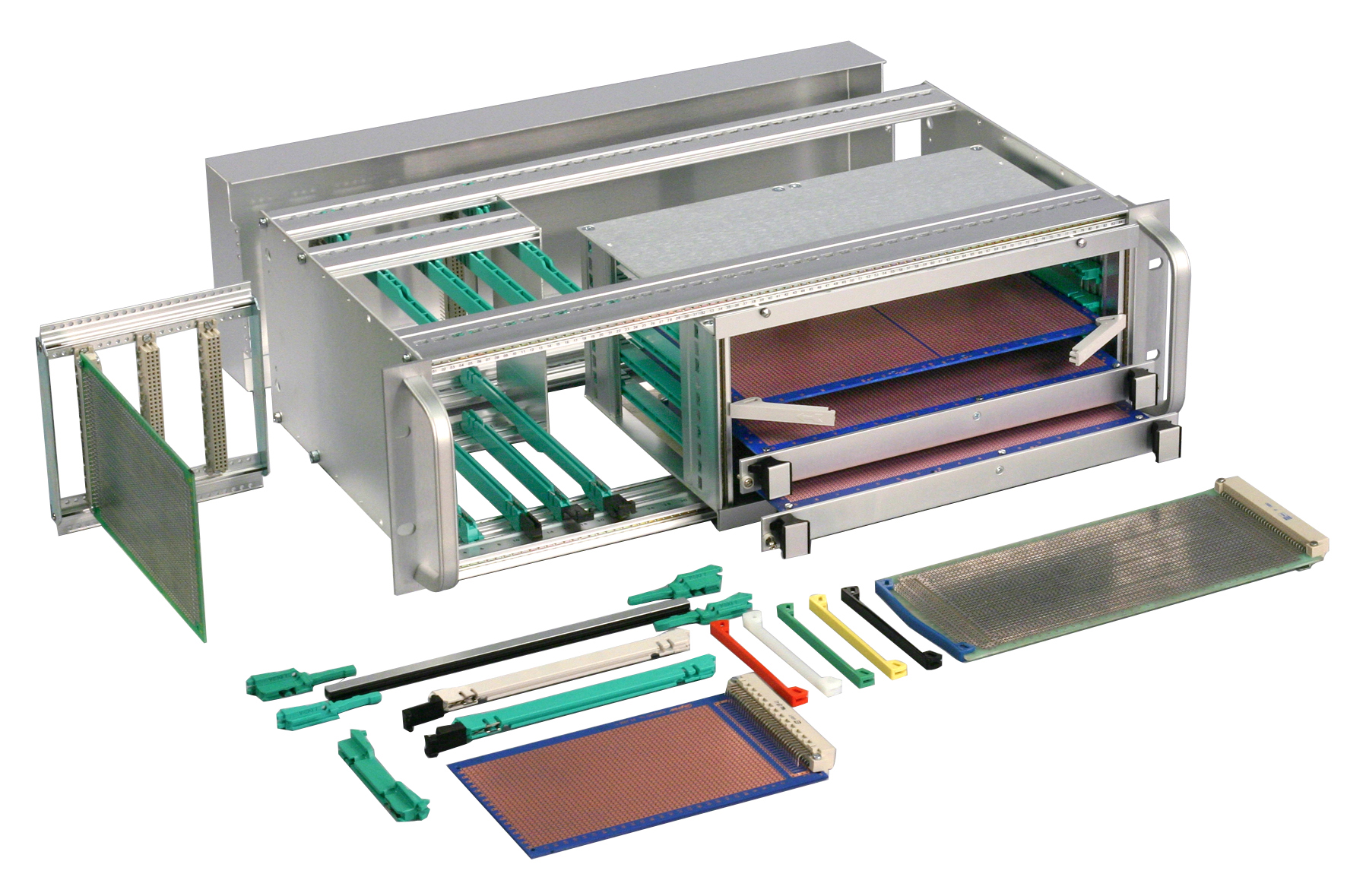
A wide range of accessories are available – from a simple tapped strip for fixing front panels, through DIN connector mounting systems and divider kits to fixings for mounting backplanes – enabling you to tailor the KM6-II subrack system to the exact requirements of your project.
Download CatalogueTapped Strips
Tapped M2,5 holes on a pitch of 1HP, these strips are used for fixing front panels, backplanes, or as an option for chassis plates. As an alternative to tapped strips, a slide nut suitable for use in front tie bars only can be used where a small number of locations are required. Also available is an M3 tapped strip for such applications as ATCA backplane mounting.
| Description | Quantity | Order Code |
|---|---|---|
| 24HP Tapped Strip | 1 | 950-202799 |
| 42HP Tapped Strip | 1 | 950-202739 |
| 60HP Tapped Strip | 1 | 950-202740 |
| 84HP Tapped Strip | 1 | 950-202001 |
| 84HP M3 Tapped Strip | 1 | 950-276330 |
| Slide Nut | 10 | 124-30499 |
DIN 41612 Connector Mounting Frame
– Converts backplane extrusions to DIN 41612 mounting
– Separate assembly and wiring possible
– 3U height
– Various widths
– Conductive finish
This frame is supplied as a kit comprising 2 aluminium extrusions with M2,5 holes on a 1HP pitch, two steel end plates and fixings.
| Description | Quantity | Order Code |
|---|---|---|
| 24HP DIN 41612 Connector Mounting Frame | 1 | 950-34247 |
| 42HP DIN 41612 Connector Mounting Frame | 1 | 950-34246 |
| 84HP DIN 41612 Connector Mounting Frame | 1 | 950-34244 |
DIN 41612 Connector Mounting Extrusions
As an alternative to the mounting frame the horizontal extrusions are available in separate kits. A 6HP version is of particular use for mounting one connector to mate with a power supply plug-in units. There is also a version at 84HP width. In both cases, the kit comprises two extrusions and fixings.
| Description | Quantity | Order Code |
|---|---|---|
| 6HP Horizontal Extrusion Separate Kits | 2 | 950-249491 |
| 84HP Horizontal Extrusion Separate Kits | 2 | 950-249489 |
Backplane Spacer Strips
Two types of spacer strips are available, insulating and conductive. The insulating type is available in one and two level versions, each having half shears to aid assembly. The two-level version is used on centre rear tie bars. The 84HP strips can be easily cut down for smaller widths. The conductive strip is 42HP wide and supplied singly.
Note: If conductive spacer strips are used in 84HP subracks please order 2 x 42HP spacer strips per tie bar.
| Description | Quantity | Order Code |
|---|---|---|
| Insulating Spacer Single Level | 1 | 950-10014 |
| Insulating Spaceer Two Level | 1 | 950-10015 |
| Conductive Spacer (42HP Only) | 1 | 173-60788 |
KM6-II Guides
A number of different guides are available to suit both standard eurocards and also 111.76/245.1mm high (3U/6U) plug-in units, in a variety of depths and card thicknesses.
Single Part Guides
Type 1 PCB For Eurocards of 1,6mm thickness, either 100mm, 160mm or 220mm long. Compatible with grounding clip & bolt-down screw.
Type 2 PCB For Eurocards of 2,4mm thickness, either 160mm or 220mm long. Not compatible with grounding clip or bolt-down screw.
Type 3 PIU For standard plug-in units (111.76 or 245.1mm height), 1.6mm thickness, 160mm or 220mm long. Not compatible with grounding clip, compatible with bolt down screw.
Type 4 PCB For Eurocards of 1,6mm thickness, 220mm long, this guide will fit over intermediate extrusions, permitting mixing of pcb depths. Compatible with grounding clip & bolt-down screw.
| Type | Application | Board Length | Quantity | Order Code |
|---|---|---|---|---|
| 1 | PCB 1.6mm Thick | 100mm | 10 | 950-242850 |
| 160mm | 10 | 950-232662 | ||
| 220mm | 10 | 950-232663 | ||
| 2 | PCB 2.4mm Thick | 160mm | 10 | 173-232666 |
| 220mm | 10 | 173-232667 | ||
| 3 | Plug-in-unit | 160mm | 10 | 950-232664 |
| 220mm | 10 | 950-232665 | ||
| 4 | Low Profile PCB | 220mm | 10 | 950-232668 |
Three Part Guides
For Eurocard PCB or PIU depths of 280mm, 340mm & 400mm, the below three part guides should be used. Comprising a centre aluminium section (with plastic insert) and two guide feet, they can easily be cut to suit other custom lengths. (Note that the centre extrusion should be cut 76mm short of the desired eurocard length, e.g. a 400mm guide would have a 324mm long extrusion).
| Type | Application | Board Length | Quantity | Order Code |
|---|---|---|---|---|
| 5 | PCB 1.6mm Thick | 280mm | 10 | 950-276108 |
| 340mm | 10 | 950-276109 | ||
| 400mm | 10 | 950-276110 | ||
| 6 | Guide Feet, PCB 1.6mm Thick | 10 Pairs | 950-202635 | |
| 8 | Guide Feet, PIU 1.6mm Thick | 10 Pairs | 950-202636 |
PCB Grounding Clip
This grounding clip can be inserted into the front or rear of 1,6mm pcb guides in KM6 subracks.
Features
– Electrostatic Protection
– Occupies ‘unused’ area of Eurocard
– No screws required
Contacts on the clip provide electrical continuity between a suitably equipped Eurocard and, via a spring under the clip to standard front extrusions. Pcb’s can, therefore, be grounded before the engagement of connectors. The clip, which is supplied in packs of 10, fits into a ‘pocket’ in the guide and requires no screw fixings to maintain contact.
The modification required to the pcb takes the form of a conductive strip along the edge of the board, either on the left or right side. The clip has been tested to IEC 950: 1986 section 2.5.11. In testing, the clip reached a steady temperature of 76 degrees C at 15A, with a resistance path of 7mΩ. A typical electrostatic discharge would be 12A for a period of 1 microsecond. It should be noted that the clip is designed to provide a ground path for electrostatic charges, not for a power short circuit or as a ground rail.
| Description | Quantity | Order Code |
|---|---|---|
| Grounding Clip | Pack of 10 | 950-251366 |
Positive Guide Retention – Tapped Strips
All KM6-II guides, with the exception of the 2,4mm slot version, can be bolted down to a tapped strip in the front extrusion to give shock and vibration resistance. Tapped strips (supplied singly) should be selected by subrack width. The screw used is M2,5 x 5mm cheesehead, supplied in a packet of 100.
| Description | Quantity | Order Code |
|---|---|---|
| 24HP Tapped Strip | 1 | 950-202799 |
| 42HP Tapped Strip | 1 | 950-202739 |
| 60HP Tapped Strip | 1 | 950-202740 |
| 84HP Tapped Strip | 1 | 950-202001 |
| Security Fixing Screws M2.5 x 5 | 100 | 173-202579 |
PCB Retainers
Card retainers are available in two types, normal and security. The normal retainer is positioned directly in front of the guide moulding and is operated by finger pressure as illustrated to release the PCB. The security retainer is designed for extra security in vibrative environments and is operated by a unique screw arrangement.
Once clipped in position in front of a PCB guide, complete security is achieved by 3 turns anti-clockwise of the retaining screw with a screw driver.
| Normal | 173-13821 |
|---|---|
| Security | 173-24768 |
PCB Injector/Ejector
PCB’s fitted with multiple DIN connectors can require very high insertion and withdrawal forces. These injector/ejectors comprise levers which fit to the PCB and saddles which are retained in front of the guide. It is recommended that guides are screwed down where insertion forces are excessive.
| Description | Quantity | Order Code |
|---|---|---|
| PCB Injector/Ejector | 10 Pairs | 950-251174 |
PCB Guide Nose
– Assists location of PCBs
– Extends existing KM6 PCB guide
The guide nose fits to standard 1,6 PCB guides, extending their length to within 5mm of the inside face of a front panel. The increased length is especially useful for locating circuit boards in subracks which are above or below eye level. It also provides a purchase point for the operation of certain types of card ejector.
| Description | Quantity | Order Code |
|---|---|---|
| PCB Guide Nose | 10 Pairs | 173-232679 |
KM6-II Front Divider Kits
KM6-II, front divider kits can be fitted after assembly of the subracks.
For use with 6U subracks, these divider kits provide a useful way to mix 3U and 6U board heights within a unit. The divider section is available in different widths, from 21HP to 84HP, and divides the subrack from either the left hand or right hand side.
The design of the kit is such that there is no loss of front panel space. It should be noted, however, that the divider plate restricts the use of ‘C’ type connectors to plug-in units of 4 HP width, or greater, at the position immediately to the left of the plate.
9U Front Divider Plate
This plate will divide a 9U subrack into 3U and 6U sections. It should be ordered in conjunction with 6U front divider kits. (The 6U plate is discarded.)
| Description | Order Code |
|---|---|
| 9U Divider Plate | 950-202622 |
Left Hand and Right Hand Divider Kit
| Height | Division | Width | Order Code |
|---|---|---|---|
| 6U | Ledt Hand Divider Kit | 21HP | 950-202604 |
| 24Hp | 950-202605 | ||
| 42HP | 950-202606 | ||
| 60HP | 950-202607 | ||
| Full Width Divider Kit | 84HP | 950-201275 | |
| 6U | Right Hand Divider Kit | 21HP | 950-202609 |
| 24Hp | 950-202610 | ||
| 42HP | 950-202611 | ||
| 60HP | 950-202612 | ||
| Full Width Divider Kit | 84HP | 950-201275 |
Rear Divider Kits & Plates
Rear Divider Kits
Rear dividers shorten the depth of the subrack by 60mm locally at the rear, and are employed when it is necessary to use mixed depth PCBs or modules within a 3U or 6U subrack. Example: where 160mm PCBs are required in a frame where the rear extrusions are set for 220mm deep PCBs. Rear dividers can be supplied as listed below (as a 6U kit), or can be configured by using 3U and 6U dividers together with rear tie bars and tapped strips which are available separately.
| Description | Quantity | Order Code |
|---|---|---|
| 6U x 36HP Right Hand Divider Kit | 1 | 950-203688 |
Rear Divider Plates
| Description | Quantity | Order Code |
|---|---|---|
| 3U Divider Plate | 1 | 950-202623 |
| 6U Divider Plate | 1 | 950-202624 |
Non Standard Width Rear Divider Extrusion
In order to produce other widths of divider kits, a larger, standard width should be modified as shown. Please note that the tie bar lengths differ depending upon whether the required divider area is left or right handed.
Cover Kits
Top and Base Cover kits
This range of top and base covers are suitable for fitting to both Standard and Universal KM6-II subracks . Two depths are available for protecting the guide area of 160mm or 220mm boards. The covers are available in ventilated or unventilated versions and can be fitted after the subrack has been assembled. A slot in the rear tie bar captures the cover and plastic clips secure it to the front. The cover can thus be easily removed for access.
| Type | Card Depth | Quantity | Order Code |
|---|---|---|---|
| Ventilated | 160mm | 2 | 950-202625 |
| 220mm | 2 | 950-202626 | |
| Unventilated | 160mm | 2 | 950-221913 |
| 220mm | 2 | 950-221914 |
Rear Cover Kits
Suitable for both Standard and Universal KM6-II Subracks, these are available in heights of 3U and 6U and are assembled to the endplates. All KM6-II endplates are pre-punched to accept these covers. The rear cover adds 41mm to the overall depth of a subrack.
| Description | Quantity | Order Code |
|---|---|---|
| 3U Rear Cover | 1 | 950-202641 |
| 6U Rear Cover | 1 | 950-202642 |
Horizontal Mounting Modules
This unit, which fits into a subrack like a 3U module, is actually a 6U x 20HP subrack on its side. This module permits the use of normal guides, front panels, plug-in units etc. and solves the problem of housing double Eurocards, i.e. 6U cards, in a 3U subrack, a situation which is frequently associated with modern bus systems.
The horizontal mounting module offers a number of additional advantages. It can be sub-assembled separately from the main subrack, and it offers “chimney” cooling between the end plates.
| Type | Depth | Quantity | Order Code |
|---|---|---|---|
| Horizontal Module | 160mm | 1 | 950-202791 |
| Horizontal Module | 220mm | 1 | 950-202972 |
| PCB Guide | 160mm | Pack of 10 | 950-232662 |
| PCB Guide | 220mm | Pack of 10 | 950-232663 |
Peripheral Mounting Adapters (PMA) & Air Baffle Cards
Peripheral Mounting Adapters (PMA)
Verotec’s peripheral mounting assemblies (PMAs) are designed to comply with industry standard IEC60297 (for standard eurocard applications) and IEEE1101.10, for use in VME64 Extensions and CompactPCI systems. Standard eurocard types use a 3mm anodised aluminium front panel with fixed handles whilst VME64x & CPCI types have chromated (conductive) front panels with RFI gasket and fixed handles. Both are supplied with fixing hardware.
Three types are available; the first is for vertically mounting a single standard 5.25”, front accessible peripheral such as a CD / DVD drive. The second is for mounting one standard 3.5”, front accessible peripheral (such as a floppy disk) and one standard 3.5”, embedded peripheral (such as a hard disk drive). The third is for mounting a single 2.5” embedded hard disk drive.
Standard IEC60297
| Module Size | Drive Type | F/P Cutout | Order Code |
|---|---|---|---|
| 6U x 12HP | 1 x 5.25" | 1 @ 41 x 147mm | 950-4001256 |
| 6U x 8HP | 2 x 3.5" | 1 @ 25 x 102mm | 950-4001257 |
| 3U x 4HP | 1 x 2.5" | N/A | 950-4002633 |
Shielded IEEE1101.10
| Module Size | Drive Type | F/P Cutout | Order Code |
|---|---|---|---|
| 6U x 12HP | 1 x 5.25" | 1 @ 41 x 147mm | 950-4001327 |
| 6U x 8HP | 2 x 3.5" | 1 @ 25 x 102mm | 950-4001328 |
| 3U x 4HP | 1 x 2.5" | N/A | 950-4005469 |
Air Baffle Cards
The air baffle card is designed to be used in vacant system slots to both close the front panel area and block airflow. In doing so, cooling air is diverted to active cards, thus maintaining the correct system airflow profile.
The air baffle card is available with or without handles, in standard 3U and 6U Eurocard hights, depths of 160mm and 220mm and is 4HP (one slot) wide. Customers also have the choice of either an unshielded (IEC60297) version or a shielded (IEEE 1101.10) version.
Standard IEC60297
| Description | Order Code |
|---|---|
| 3U x 160 With Handles | 950-4001329 |
| 3U x 160 Without Handles | 950-4001330 |
| 3U x 220 With Handles | 950-4001331 |
| 3U x 220 Without Handles | 950-4001332 |
| 6U x 160 With Handels | 950-4001333 |
| 6U x 160 Without Handles | 950-4001334 |
| 6U x 220 With Handles | 950-4001335 |
| 6U x 220 Without Handles | 950-4001336 |
Shielded IEEE1101.10
| Description | Order Code |
|---|---|
| 3U x 160 With Handles | 950-4001337 |
| 3U x 160 Without Handles | 950-4001338 |
| 3U x 220 With Handles | 950-4001339 |
| 3U x 220 Without Handles | 950-4001340 |
| 6U x 160 With Handels | 950-4001341 |
| 6U x 160 Without Handles | 950-4001342 |
| 6U x 220 With Handles | 950-4001343 |
| 6U x 220 Without Handles | 950-4001344 |
Subrack Handles
These handles are identical to those supplied in the KM6-II subrack kit, and offered here as accessories to the KM6 range.
| Height | Overall Height | Centre to Centre Fixing | Quantity | Order Code |
|---|---|---|---|---|
| 3U | 116.3mm | 108.3mm | 1 | 50-10117 |
| 4U | 160.8mm | 152.8mm | 1 | 50-10116 |
| 6U | 249.7mm | 241.7mm | 1 | 50-10118 |
| Screw M3.5 x 10 Countersunk Head | Pack of 10 | 173-10036 |
Rear Hinged Connector Mounting Panel, Framing Kit & Connector Protection Plates
Rear Hinged Connector Mounting Panel
This hinged rear panel provides a means of mounting plugs and sockets, and extends the depth of the subrack by 76,2mm. This extension in depth gives sufficient additional space between the backplane and the rear panel to allow wiring to the connectors.
| Description | Order Code |
|---|---|
| Hinged Rear Connector Mounting Panel | 950-202746 |
Framing Kit
For applications such as the addition of an overall rear panel or where a subrack is reverse mounted on a wall or electrical panel, for instance, this kit provides an aesthetically pleasing frame. It is available in three heights, and a standard width of 84HP.
| Dimensions | Quantity | Order Code |
|---|---|---|
| 3U x 84HP | 1 | 950-222331 |
| 6U x 84HP | 1 | 950-222332 |
| 9U x 84HP | 1 | 950-222333 |
Connector Protection Plates
Suitable for 3U/6U subracks, designed to protect connectors and wiring against damage. The plates bolt onto pre-drilled positions on the subrack endplates and add 30mm to the overall depth of the subrack.
| Description | Quantity | Order Code |
|---|---|---|
| Connector Protection Plate | 2 | 950-202751 |
Chassis System
The chassis system offers a method of mounting simple plates into subracks. They can be used for carrying additional components such as power supplies, or for securing wiring etc. The components of this system are designed for maximum versatility.
The extrusion has an M4 section which will accept hex nuts or screws directly and a section which will accept a KM6-II tapped strip or M2,5 hex nuts and screws. The extrusion is tapped M4 for fixing and our standard subrack kits have additional holes to provide convenient mounting centres.
| Description | Unit | Order Code |
|---|---|---|
| Chassis Extrusion, 42HP | Each | 956-242701 |
| Chassis Extrusion, 60HP | Each | 956-242702 |
| Chassis Extrusion, 84HP | Each | 956-242703 |
| Screws M2.5 x 8 Hex Head | Pack of 100 | 956-243262 |
| Screws M4 x 8 Hex Head | Pack of 100 | 956-243263 |
| M2.5 Hex Nuts | Pack of 100 | 27-1319 |
| M4 Hex Nuts | Pack of 100 | 956-243264 |
| Extrusion Fixing Screw M4 x 12 Pan Posi | Pack of 100 | 956-243261 |
Subrack Fixings
| Fixing Function | Type | Quantity | Order Code |
|---|---|---|---|
| End Plate to Tiebar Extrusions | M4 x 25 Skt Cap | Pack of 100 | 950-202734 |
| Connector to Rear Tiebar | M2.5 x 6mm | Pack of 100 | 173-12530 |
| Backplane to Backplane Extrusion | M2.5 x 5mm | Pack of 100 | 173-202579 |
| Guides to fron Tie Bar | M2.5 x 6mm | Pack of 100 | 173-12530 |
| Backplane to Backplane Extrusion | M2.5 x 8 | Pack of 100 | 41-227257 |


