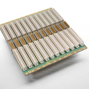
CompactPCI Backplanes
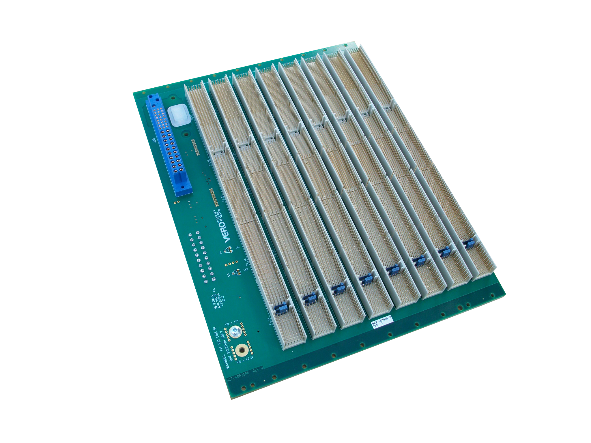
CompactPCI is an adaptation of the Peripheral Component Interconnect (PCI) specification, rev.3, for industrial and/or embedded applications that require a more robust mechanical form-factor than (but electrically compatible to) normal desktop PCI. Verotec design and manufacture a range of backplanes conforming to the below specifications / standards:
CompactPCI – Core (PICMG 2.0 Rev.3) Packet Switching (PICMG 2.16) Computer Telephoney (CT/H.110) CompactPCI Plus I/O (PICMG 2.3) CompactPCI Serial (PICMG cPCI-S.0)
CompactPCI - Core (PICMG 2.0 Rev.3)
Our standard range of high performance, hot swap, CompactPCI backplanes are available in 3U, 6U & 9U form factors and from 2 to 16 slots wide*. The generic base design allows many different product configurations to be realised (32/64Bit, 33/66MHz, left/right system slot, 5v/3.3v I/O signalling voltage and rear connections, power options etc.) making them suitable for a wide range of end user applications. * Note: A rear pallet bridge is required for backplanes above 8 slots wide – these are included with the backplane
Packet Switching (PICMG 2.16)
PICMG 2.16 supplements the robust, reliable and hot-swap capable CompactPCI architecture with the easily integrated, low-cost, high performance, and extensible Ethernet. The 2.16 specification extends rather than replaces CompactPCI because it over-lays, on the P3 connector, up to two embedded switched Ethernet networks in a star-topology. Slots can be routed either as “Fabric” or “Node” slots with a separate system / controller slot if required.
Computer Telephoney (CT/H.110)
On CT/H.110 backplanes, the P4 connector is used for implementing the H.110 TDM bus signals as well as the telecom power rails and control signals. It has 3 different mating length pins and is selectively loaded in order to meet the hazardous voltage safety requirements. The P5 connector is used for telephony I/O with 3 mating levels provided according to the pin assignments.
Compact PCI Plus I/O (PICMG 2.3)
Designed as a migration path to CPCI Serial (below), PICMG 2.3 adds fast serial data transfer, and is backward-compatible to CompactPCI (PICMG 2.0). It defines the pin assignment of the user-defined pins on the J2 connector (PICMG 2.0), sufficient for 4 PCI Express x1 links, 4 SATA, 4 USB 2.0, as well as 2 Ethernet 1000BaseT interfaces to the backplane. The new standard uses a different 2mm connector with 5 Gb/s to support the new high frequency signals. Even though signal pins are individually shielded and independent of the other pins, the connector is completely compatible to CompactPCI. This means a CompactPCI 2.3 CPU can be operated in a PICMG 2.0 system.
CompactPCI Serial (PICMG CPCI-S.0)
Whilst adopting some key, proven features of CompactPCI (PICMG 2), the cPCI-S.0 standard does away with the traditional PCI parallel bus completely and defines a point-to-point (serial) topology. The system slot provides 8 x PCI Express, SATA, USB (2&3) and Ethernet 10GBASE-T interfaces whilst the peripheral slots provide one of each of the above except Ethernet where up to 8 connections are offered. A different connector arrangement means there is no backward compatibility with PICMG 2.0.
Ordering Information
The below table should be used to configure a unique part number for the CompactPCI backplane required. Note that not all combinations are possible and not all options are applicable.
Order Code : 927- _ _ _ _ _ _ _
| Specification | 1st Digit | 2nd Digit | 3rd Digit | 4th Digit | 5th Digit | 6th & 7th Digit |
|---|---|---|---|---|---|---|
| CompactPCI (PICMG 2.0 Rev.3) | 5 | |||||
| Packet Switching (PICMG 2.16) | 6 | |||||
| Computer Telephoney (CT/H.110) | 7 | |||||
| CompactPCI Plus I/O (PICMG 2.3) | 8 | |||||
| CompactPCI Serial (PICMG cPCI-S.0) | 9 | |||||
| Bandwidth / I/O Voltage / Clock Speed | ||||||
| N/A | 0 | |||||
| 32Bit, 3.3V, 33MHz | 1 | |||||
| 64Bit, 3.3V, 33MHz | 2 | |||||
| 32Bit, 5.0V, 33MHz | 3 | |||||
| 64Bit, 5.0V, 33MHz | 4 | |||||
| 32Bit, 3.3V, 66MHz | 5 | |||||
| 64Bit, 3.3V, 66MHz | 6 | |||||
| 32Bit, 5.0V, 66MHz | 7 | |||||
| 64Bit, 5.0V, 66MHz | 8 | |||||
| Form Factor / System Slot Orientation | ||||||
| 3U, left hand | 1 | |||||
| 6U, left hand | 2 | |||||
| 3U, right hand | 3 | |||||
| 6U, right hand | 4 | |||||
| 6U+3U (Horizontal Mounting), left hand | 5 | |||||
| 6U+3U (Horizontal Mounting), left hand | 6 | |||||
| Topology and I/O Connections | ||||||
| Parallel Bus, no I/O connectors | 0 | |||||
| Parallel Bus, with I/O connectors | 1 | |||||
| Single Star, no I/O connectors | 2 | |||||
| Single Star, with I/O connectors | 3 | |||||
| Dual Star, no I/O connectors | 4 | |||||
| Dual star, with I/O connectors | 5 | |||||
| Full Mesh, no I/O connectors | 6 | |||||
| Full Mesh, with I/O connectors | 7 | |||||
| Power-On Options | ||||||
| Power Bugs (M6 screw) | 1 | |||||
| 6.3mm Faston Blade | 2 | |||||
| Power Bugs with Busbar (M6 screw) | 3 | |||||
| ATX Connector | 4 | |||||
| Single P47 Positronic | 5 | |||||
| Dual P47 Positronic | 6 | |||||
| Triple P47 Positronic | 7 | |||||
| Slot Width | ||||||
| 01-21 slots | 01-21 |


